Introduction to HN48D Dual purpose Fuel Controller
1. Product Introduction
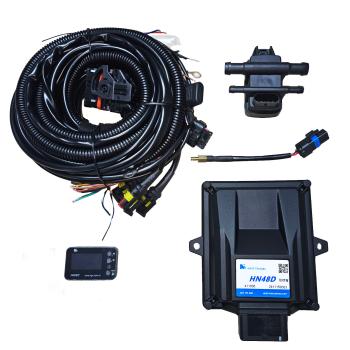
The HN48D dual fuel controller is a newly developed dual fuel control unit by our company, suitable for the aftermarket and foreign trade markets, mainly designed to cope with dual nozzle (DIS) models. The HN48D controller is suitable for vehicles with 4 cylinders and 8 injectors. By collecting all 8 fuel injectors centrally into the ECU and controlling the injection of 4 gas nozzles through merging calculations. The implementation scheme of installing an external nozzle simulator for dual nozzle models has been eliminated. At the same time, it also eliminates the need for dual nozzle models to achieve injection through an 8-cylinder controller, reducing the installation of a set of gas nozzles.
The HN48D controller solves the shortcomings of conventional solutions that cannot adapt to DIS models with asynchronous injection through creative acquisition and injection control methods, and also has excellent performance in driving and acceleration.
2. Scope of application
(1) Suitable for dual fuel (gasoline, natural gas) naturally aspirated models.
(2) Specially adapted for dual nozzle models
(3) Currently, the following dual nozzle models are perfectly compatible:
(4) Nissan Sylphy, Sunshine, Bluebird; Hyundai Elantra 1.5L, Kia K3 KX3¡¢ Buick 3-cylinder 1.0L
3. Main features
(1) Suitable for 4-cylinder 4-nozzle, 4-cylinder 8-nozzle, 3-cylinder 3-nozzle, 3-cylinder 6-nozzle
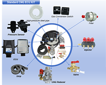
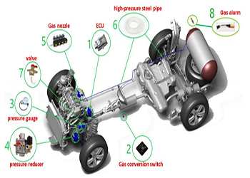
(2) Support NGV gas leak detector
(3) Support NGV LCD multifunctional display switch
(4) Fault diagnosis function
(5) Support communication function between CAN bus and gasoline ECU
(6) 48PIN automotive grade connector
(7) Must be paired with a dual nozzle dedicated wiring harness and cannot be used interchangeably with a regular HN48 controller wiring harness
4. Wire harness performance
(1) The wire operates reliably within the temperature range of -40 ¡ã C to 125 ¡ã C.
(2) All connections of the wiring harness are insulated from each other and there is no short circuit phenomenon.
(3) The wiring harness has EMC capability, as well as anti loosening, waterproof, and anti gas properties.
(4) Compliant with relevant national standards and automotive industry standards
5. Shell size and installation
(1) Shell Overview
The casing of the controller consists of upper and lower parts, with the upper casing made of PA6GF30 and the lower casing made of galvanized steel plate, and assembled with silicone sealing. The surface of the casing must not have sharp burrs or edges. The product has high structural strength and rigidity, and uses sealed silicone waterproofing inside. Thermal conductive silicone grease is laid between the bottom plate and PCB board to dissipate heat through the bottom plate.
(2) Installation requirements
The controller is installed on the entire vehicle. In order to ensure its normal and reliable operation, the installation and usage requirements are as follows:
(3) Temperature requirements for working environment
A. Operating temperature range: -40 ¡æ to+105 ¡æ. If the temperature exceeds the range, cooling should be used;
B. Pay attention to placing the controller in a location with good air flow;
C. Avoid drastic temperature changes;
D. Avoid the accumulation of dirt (mud, dust, air pollution, etc.) on the surface of the controller, otherwise it may cause damage to the heat dissipation capacity.
(4) Installation location requirements
A. The ventilation is good, and it is strictly prohibited to have coverings on the controller to avoid scaling caused by long-term use;
B. Stay away from heat sources (such as exhaust pipes) and avoid thermal radiation to the controller; Prevent the heat flow generated by the heat source from directly acting on the controller;
C. Stay away from high-frequency and high-energy sources;
D. When installing, it is advisable to choose a relatively high and dry location to avoid moisture, water immersion, mud and water splashing, and sand and stone impact; Avoid contact with corrosive liquids;
E. The wiring harness near the controller should be securely fixed to prevent vibration caused by instability from affecting the controller;
F. Prevent installation in locations with high vibration;
G. Ensure electromagnetic shielding;
H. Consider installing protective covers, radiators, and other devices as appropriate;
I. The selection of installation location should be based on the convenience of loading, unloading, and maintenance.
(5) Installation direction requirements
A. Try to use an installation method with an appropriate inclination angle at the top to prevent water from accumulating on the surface;
B. It is best to connect the wiring harness from the side;
C. Wiring harnesses are not allowed to be connected to the upper part of the controller.
6. Assembly and use
(1) Controller assembly and wiring harness connectors
The controller connector has error prevention function to prevent incorrect insertion of the wiring harness. All mating terminals of the controller terminal harness connector must use the wiring terminals corresponding to the harness connector model defined in the customer's drawing. The HN48D controller must be equipped with a dual nozzle dedicated wiring harness and cannot be interchanged with a regular HN48 controller wiring harness.
7. Precautions
(1) When assembling the controller and wiring harness connectors, it is essential to ensure that the system power is disconnected, i.e. the engine or vehicle ignition switch is in a power-off state.
(2) Do not plug or unplug the controller while the ignition switch is turned on.
(3) Avoid touching the controller pins or exposed parts of the controller harness with any part of the body while it is live.
(4) Do not use controllers with obvious physical damage to their appearance. The surface of the controller casing shall not be coated with any unapproved materials, and it is not allowed to spray paint or other insulating liquids on the pins of the controller.
(5) When using electric welding to repair vehicles, the controller must be disconnected and unplugged, otherwise it may burn out the controller.
(6) Do not use any tools or other objects to strike any part of the controller, and do not modify, adjust, or disassemble it.
(7) When wiring the fuel injector, ensure that the nozzles on the same side are connected to the same set of wiring harnesses.
8. Fault analysis and troubleshooting
The controller will continuously monitor the gas alarm, gas nozzle, gasoline ECU related circuits, battery voltage, and even the controller itself, and perform reliability checks on sensor output signals, actuator drive signals, and internal signals.
When the vehicle engine system malfunctions, the following methods should be followed for handling:
Turn the key switch to the ON position, use a diagnostic tool to read the fault information in the controller to determine the specific fault, and check the relevant sensors and actuators. If the fault cannot be resolved, please record the fault information and pass it on to NGV's after-sales service engineer.
9. Other matters
(1) Storage and transportation
During transportation, the controller should be handled with care and excessive stacking of packaging boxes should be avoided to prevent damage to the controller.
The controller should be stored in a cool, dry, and dust-free environment, and must not be exposed to liquid contaminants.
(2) Receipt and Inspection
The receiving party should check each packaging box to confirm whether the label and part number on the packaging box are consistent with the required part number for supply. If any damage is found, it must be promptly reported to the relevant departments of Hesheng Hydrogen En.
Inspection content:
A. Check if the label of the controller complies with regulations;
B. Check if there is any obvious physical damage to the casing of the controller;
C. Check if there is any physical damage to the connector housing and terminals of the controller.
10. After sales service
Conduct matters in accordance with the terms of the quality assurance agreement signed between the customer and Hesheng Hydrogen En.
Popular articles
-
How the CNG Automotive S
Compressed natural gas (CNG) automotive systems
-
What Is CNG Pressure Red
The pressure reducer of natural gas vehicle is
-
Advantages Of CNG Gas V
Compressed natural gas vehicles are vehicles th
-
Reasons For High Gas Con
1. Original vehicle condition A. The tec
-
Differences Between Sing
Characteristics of Gas Single Point Device
-

How To Improve The Power
1. Install ignition advance angle What i
-

Advantages And Principle
LPG and CNG are two mainstream alternati
-

How The CNG Gas Vehicle
If you want to know ¨C how does the CNG conversi


Latest comments
0piece comment
no comments, welcome to comment¡£