


Key points for debugging oil to gas vehicles
1�� First, heat the car with oil. Generally, when the water temperature reaches 70 degrees, turn it to the gas.
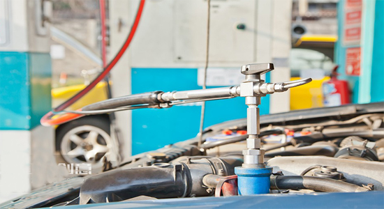
2�� Connect a pressure gauge weighing less than 3 kilograms to the spray rail. Under normal idle conditions, the pressure on the spray rail should be between 0.8-1.2 kilograms for natural gas and 0.3-0.7 kilograms for liquefied gas. During a road test, if the power is insufficient, increase the pressure. If the power is sufficient, reduce the pressure.
3�� Idle speed adjustment:
1. Unstable idle speed:
(1) It may be a cylinder shortage, whether it is a lack of oil or gas. If both oil and gas are lacking, find the corresponding male plug of the cylinder shortage signal line for poor contact. If there is no shortage of oil or gas, check the reliable contact of the injection rail plug of the missing cylinder. It is also possible that the spark in this cylinder is weak.
(2) Possible weak ignition, check if the cylinder line and spark plug are normal.
(3) It may be that the air filter is too dirty, clean or replace it.
(4) The pressure regulator is not constant, replace the regulator.
4�� Insufficient power:
1. Check if the pipeline is unobstructed.
2. Is the ignition normal.
3. Is the air filter clean.
4. Some cars require early ignition.
5�� Unable to turn to gas:
1. Poor grounding of the switch.
2. The switch is out of power.
3. The switch is not functioning properly.
4. Is the wiring harness functioning properly.
5. Is the signal line connected correctly.
6�� Oil and gas co firing:
1. First, check if the relay is connected correctly.
2. Is it working properly.
3. The live line of the fuel injector should be controlled by the gas computer.
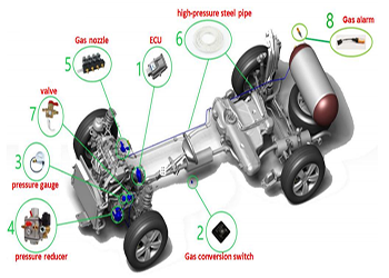
CNG vehicle power enhancement
After the car is converted from gasoline to gas, there may be insufficient or faulty phenomena such as mixed combustion of oil and gas, decreased power, poor acceleration performance, high gas consumption, malfunction indicator light on, and backfire. By correctly installing and debugging ignition advance angle controllers and simulation controllers, selecting appropriate spark plugs, and adjusting power valves and idle valves, it is possible to effectively overcome the shortcomings and eliminate various faults of natural gas vehicles after modification. This is a necessary measure to ensure the effectiveness of oil to gas conversion in automobiles.
1�� After the car oil to gas conversion, an ignition advance angle controller must be installed
��1�� The importance of installing an ignition advance angle controller
The main component of natural gas is methane, with a ignition point of over 650 degrees Celsius. Its chemical properties are relatively stable and not easy to ignite. Its combustion rate is slightly lower than gasoline, and its explosive pressure is lower than gasoline. In the use of natural gas/gasoline dual fuel vehicles, in order to ensure the normal operation of both fuels, the compression ratio of the engine is generally the same as that of a gasoline engine. When using natural gas, the advantage of high octane value of natural gas cannot be fully utilized. In addition, a constant compression ratio cannot meet the different requirements of the ignition delay and combustion speed of the two fuels. The ignition advance angle has a strong correlation with the compression ratio and is easy to change. When using natural gas, a larger ignition advance angle is allowed due to its high octane rating. At the same time, because the combustion speed of natural gas is lower than that of gasoline, a larger ignition advance angle is also required. To improve the thermal efficiency of natural gas, the advance angle must be increased by 8-15 degrees relative to gasoline. If the ignition advance angle of the original engine is not changed, there will be a delay in the starting point of the fuel, a low rate of cylinder pressure increase, low combustion temperature, increased heat transfer loss, increased exhaust temperature, and decreased thermal efficiency when using natural gas. Therefore, it is necessary to install an adaptive fuel ignition advance angle controller that can ensure the best ignition advance angle for both natural gas and gasoline fuel operating conditions, so that the ignition advance angle can adaptively change with the change of fuel.
��2�� The function of ignition advance angle controller
The ignition advance angle controller can ensure stable combustion of natural gas and increase engine power by appropriately advancing the ignition advance angle without changing the original engine structure. The ignition advance angle controller enables natural gas/gasoline dual fuel vehicles to automatically change the ignition advance angle when using different fuels, ensuring that the engine operates at the optimal ignition advance angle at different speeds. It can balance both fuel and gas conditions, while not changing the original engine compression ratio and combustion structure. The ignition advance angle controller can achieve precise control of different ignition advance angles for dual fuel vehicles through microcontroller control based on the position of the fuel conversion switch. The installation of this adaptive ignition advance angle controller increases the power and torque of the car engine, while reducing energy consumption. This adaptive fuel ignition advance angle controller can improve the power and fuel economy of the dual fuel car engine to a certain extent, and has a significant improvement effect on solving the problems of poor uphill acceleration performance, high gas consumption, and backfire after the vehicle is converted from oil to gas.
��3�� Regarding the installation and debugging of ignition pre starter
1. Installation precautions:
(1) Confirm that the wiring harness settings of the ignition igniter are consistent with the vehicle model that needs to be modified.
(2) During installation, it should be kept away from rainy, damp, and high-temperature areas
(3) Keep away from ignition high-voltage lines and maintain good insulation.
2. Wiring
(1) A short wire harness with a connector is usually not used, but can be connected for vehicles with corresponding sensors.
(2) A wiring harness with a pair of plugs, connected to the crankshaft position sensor.
(3) In wiring harnesses without connectors:
�� Red line: 12V power supply, connected to ignition switch.
�� Black wire: power ground wire, ground wire.
�� Blue line: switch control, connected to the gas output of the conversion switch.
�� Yellow line: throttle control, connected to throttle position sensor.
Different manufacturers may have different wire harness colors, but the wiring principle is the same.
3. Switch settings
There are three micro switches on the ignition advance angle controller, and the setting of the advance angle is completed by switches 1 and 2. The specific method is shown in Table 1. According to actual testing, the appropriate angle should be 12o or 15o. Different vehicle models have different requirements, and it should be determined based on the actual testing results. The vehicle model is set by switch 3, which is usually set to OFF in domestic cars,
Special models such as Volvo are set to ON
The specific setting method is detailed in Table 1
4. Debugging precautions:
(1) Adjust the adjustable potentiometer clockwise to the end. At this moment, the red light-emitting tube lights up. Add ignition advance angle.
(2) Adjust the adjustable potentiometer counterclockwise until the red LED goes out. At this point, do not change the ignition advance angle.
(3) After adjustment, in the gas state, the red luminous tube lights up when accelerating and goes out when not accelerating.
5. Determination of throttle sensor signal line: The throttle sensor is located near the throttle valve and has three lines. It is measured with a multimeter in AC voltage range. The red probe is connected to any of the three wires in the plug, and the black probe is grounded. The voltage should be around 0.5V at idle speed. As the engine speed increases, the voltage should also increase. Otherwise, it is the other two wires. Determine them one by one until they are found.
3�� The method of using CNG to troubleshoot the faulty light
Simulation controllers must be installed after the conversion of gasoline to gas in automobiles
��1�� The problem of not adding a simulator:
Traditional carburetor cars use an oil gas switch to cut off the oil pump circuit during gas burning, stop the oil pump from continuing to pump oil, and prevent oil and gas mixing. Nowadays, cars are all controlled by microcomputers, and the oil to gas conversion of electronic fuel injection vehicles. On the one hand, in order to prevent the fuel injector from being blocked due to long-term use, it is required to start with oil every time it is started, and then switch to gas burning operation. In this way, nearly 2L of gasoline will be stored in the pipeline between the oil pump and the fuel injector after each oil pump is started, burning together with the gas. This does not completely eliminate the mixing of oil and gas, and the more times it is started every day, the more gasoline will be consumed. This is the fundamental reason for the inexplicable decrease in gasoline after the oil to gas conversion of electronic fuel injection vehicles. In addition, the fuel injector is always in the open state, whether it is in gas or fuel burning state, which is not conducive to extending the life of the fuel injector. So when the fuel to gas conversion of an electronic fuel injection vehicle cuts off the fuel pump circuit, the fuel injector circuit should also be cut off synchronously, but the fuel injector circuit cannot be cut off solely with a regular switch, otherwise the original car computer cannot detect the existence of the fuel injector signal and will enter a fault mode. This requires that while cutting off the fuel injector circuit, a virtual signal indicating that the fuel injector circuit is still working should also be sent to the original vehicle ECU. On the other hand, due to the differences in the inspection and signal sent by the original vehicle's oxygen sensor during gas combustion compared to fuel combustion, the self-learning function of the original vehicle's ECU will remember the state when using CNG. The gasoline ECU will perceive this as a fault and record it, and enter the fault mode. When switching to using gasoline, it will affect the control process of gasoline and seriously affect the working process of gasoline, mainly manifested as unstable idle during fuel combustion, poor fuel supply, weak acceleration, and "spitting" of the vehicle during driving. As a result, when the vehicle burns natural gas for a period of time and then re burns it, the fuel consumption increases significantly or it cannot operate normally at all. Dual fuel vehicles have shrunk to cars that can only burn gas but not oil. The existence of this defect has hindered the full utilization of dual fuel steam efficiency, causing unbearable suffering for a large number of users, Some users even removed their gas devices and completely abandoned the use of natural gas, resulting in a waste of modification investment, which has become a bottleneck for the development of natural gas vehicles.
��2�� The role of natural gas vehicle signal simulation controller
To avoid any impact on the fuel system, dual fuel vehicles should adopt a signal simulation controller to solve this interference problem. The function of the signal simulation controller is to stop the action of the fuel injector when using natural gas, simulate the signal of one fuel injector still in action and the simulated signal of the oxygen sensor that is the same as the fuel, so that the original gasoline ECU senses the same gas as the fuel, thereby providing normal ignition management and control functions. It can take into account both fuel and gas conditions to ensure that dual fuel vehicles can work normally in both fuel and gas states. It is of positive significance to improve the current shortcomings of natural gas vehicles and fully tap into their potential.
��3�� Installation and Debugging of Signal Simulation Controller
1. Installation precautions:
(1) Confirm that the wiring harness of the signal simulation controller is consistent with the vehicle model that needs to be modified.
(2) During installation, it should be kept away from rainy, damp, and high-temperature areas
(3) Keep away from ignition high-voltage lines and maintain good insulation.
2. Wiring
The wiring of the simulator is divided into three bundles, one is the wiring harness connected to the nozzle, one is the wiring harness connected to the oxygen sensor, and one is the power wiring harness. During installation:
(1) Remove the nozzle harness of the original vehicle from the nozzle and plug it into the corresponding connector of the simulator harness. Insert the other connector on the simulator harness into the nozzle.
(2) White and yellow wires: To connect the wiring harness of the oxygen sensor, first cut off the oxygen sensor signal output wire. Connect the oxygen sensor signal output end to the white wire and the end leading to the original car computer to the yellow wire (note: for the convenience of replacing the oxygen sensor, it is usually cut off after the oxygen sensor plug).
(3) In the power harness, the blue wire is connected to the gas output terminal of the conversion switch, and the black wire is connected to the negative terminal (ground) of the power supply.
Different manufacturers or wire harness colors may vary, but the wiring principle is the same.
3. Switch settings
There are two micro switches on the simulator, and the specific setting method is shown in Table 2. Generally, the first type is set. If the setting is incorrect, the simulator will not work and the car's fault light will still be on. Remember to
4. Determination of oxygen sensor signal output line
First, find the oxygen sensor. Generally, an oxygen sensor has four wires, of which only one is the signal connection wire between the oxygen sensor and the engine ECU. Set the multimeter to the DC voltage range and select the 2.5V range. Connect the red probe of the multimeter to any wire in the oxygen sensor plug, and ground the black probe. In the burning state, the DC voltage output from the oxygen sensor signal wire to the engine ECU should fluctuate between 0-1V, about 7 times every 10 seconds. Otherwise, it will be the other three wires. Judge them one by one until they are found.
5. Precautions for Oxygen Sensor Measurement
A high internal resistance voltmeter should be used to measure the oxygen sensor to prevent damage during testing. In addition, the range of the voltmeter should be 2V DC, and a pointer type voltmeter should be used for easy observation.
6. Adjustment method for simulator signal frequency
In the combustion mode, use a DC voltmeter to measure the ground voltage at the connection end between the simulator and the original vehicle ECU, and the output voltage should fluctuate between 0.2-0.8V,
Adjust the potentiometer of the simulator until the fluctuation frequency of the simulated signal between 0.2-0.8V is the same as when burning oil, which is still about 7 times every 10 seconds.
3�� Does direct injection modification also require the installation of ignition advance angle controller and simulator
This issue cannot be generalized. The key is whether the newly installed gas computer itself has automatic ignition advance angle adjustment and oxygen sensing functions. Gas computers produced by different manufacturers have different functions and prices. Some simplified versions of gas computers only have oil pump cut-off and nozzle simulation functions, without ignition advance angle adjustment and oxygen sensing functions. This requires the addition of an ignition advance angle controller, which provides better power and lower gas consumption on the existing basis. Adding a simulator can eliminate some inexplicable strange phenomena after oil to gas conversion. How can one determine whether the newly installed gas computer has these two functions? Before modification, check the installation instructions and wiring diagram of the gas computer. After modification, check the actual wiring on the car. If the gas computer has reserved plugs and wires for connecting the original crankshaft position sensor and throttle sensor, it indicates that the gas computer has the function of adjusting the ignition advance angle. Otherwise, it is the opposite. If the gas computer has two wires connected to the original vehicle oxygen sensor, it indicates that the gas computer has oxygen sensing simulation function. Otherwise, it does not. However, it should be noted that some gas computers also have one wire connected to the oxygen sensor, but only one wire. This wire uses the original vehicle oxygen sensor to detect the properties of the exhaust gas during combustion, and feeds back a signal to the gas computer to control the real-time injection volume of the four nozzles. It does not have oxygen sensing simulation function. The most obvious feature of gas computers with oxygen sensing simulation function is that the wires connected to the oxygen sensor are two instead of one. For gas computers without oxygen sensing simulation function, a simulation controller must be installed.
4�� After the car oil to gas conversion, it must be replaced with "natural gas specific spark plugs"
Due to the lower combustion speed of natural gas compared to gasoline, a larger amount of ignition energy is required, which cannot be met by ordinary car spark plugs. After replacing with various spark plugs, actual tests have shown that the Xianghuoju 3-pole "natural gas special spark plug" (model 5407) can better meet the needs of natural gas combustion. This spark plug has a market reference price of 8 yuan per piece, which costs more than 30 yuan per car. The gas and oil burning effect is very good. In this issue, do not blindly believe in the so-called imported spark plug. It is more expensive to buy it, it is better to buy it correctly, and the best one is suitable.
5�� The solution to stalling in neutral or by stepping on the clutch when burning gas at high speeds after oil to gas conversion
The reason for stalling is that the intake of air increases at high speeds, causing the mixture in the cylinder to be too lean. If direct injection is used, the gas computer data can be adjusted using a PC to increase the injection of CNG or replace the injection rail with a slightly larger injection hole. If self-priming is used, the idle valve on the pressure reducing valve can be adjusted to increase the supply of CNG. The simplest method is to use a sealing tape to partially seal the air intake pipe, which aims to reduce the intake of air at high speeds and indirectly increase the concentration of the mixture in the cylinder during combustion. This method has little effect on combustion, but during oil combustion, due to the reduction of the intake area, the intake of air decreases, which may cause problems. The problem of rich mixture and increased fuel consumption is a concern, so this method can be used for modified vehicles that rarely burn fuel, For vehicles that frequently switch between oil and gas (such as long-distance use of commonly used oil), try to use other methods as much as possible.
6�� Adjustment method of power valve after oil to gas conversion
The power valve is a valve on the air pipe connected to the original intake manifold. After the engine runs for 10 minutes, the water temperature gauge rises to the middle, and the engine is accelerated to raise the tachometer to 3000 revolutions per minute. At this time, first rotate the power adjustment nut clockwise until the engine speed decreases, and then rotate the nut counterclockwise until the engine speed increases. Find the position of the adjustment nut when the engine speed increases or decreases, and then turn the nut counterclockwise to 90o~180o.
7�� Adjustment method of idle valve after oil to gas conversion
The idle valve is a screw on the pressure reducing valve. The idea is to keep the engine speed at around 1000 revolutions per minute. Adjust the idle screw by turning it clockwise and then counterclockwise. As the screw is adjusted, the engine speed changes accordingly. Adjust the adjusting screw to the position where the engine speed is at its highest.
8�� The effectiveness of oil to gas conversion depends on three aspects of guarantee
After the oil to gas conversion, many people have reported various problems. Whether the effect of the car's oil to gas conversion is good or not involves three aspects: first, it is necessary to add an ignition advance angle controller and a simulation controller, and ensure that the wiring and debugging are correct; The second is to adjust the idle valve and power valve correctly, and the third is to replace the multi pole "natural gas special spark plug. As long as the above three aspects are guaranteed, the oil to gas conversion effect should be very good. Taking my vehicle as an example, after the oil to gas conversion, it has run nearly 50000 kilometers with strong power, almost no different from oil.
The pictures and articles are from the internet. If there is any infringement, please contact us to delete them
Popular articles
-
How the CNG Automotive S
Compressed natural gas (CNG) automotive systems
-
What Is CNG Pressure Red
The pressure reducer of natural gas vehicle is
-
Advantages Of CNG Gas V
Compressed natural gas vehicles are vehicles th
-
Reasons For High Gas Con
1. Original vehicle condition A. The tec
-
Differences Between Sing
Characteristics of Gas Single Point Device
-

How To Improve The Power
1. Install ignition advance angle What i
-

How The CNG Gas Vehicle
If you want to know �C how does the CNG conversi
-
Advantages And Principle
LPG and CNG are two mainstream alternati


Latest comments
0piece comment
no comments, welcome to comment��